In the first post of this series we discussed the background of the project: http://voxelwise.com/2025/11/ti-86-overhaul-backstory/
In the second post we did the reverse engineering to understand the display data for the TI-86: http://voxelwise.com/2025/11/ti-86-overhaul-screen-data-protocol/
Now, let’s use what we know and send that data to a new display.
Decision: Which screen?
A useful starting point is finding a screen that will actually fit inside the TI-86 chassis. The glass area of the existing LCD is 71mm wide, about 51 mm tall, and 81.5mm diagonal. The display PCB is a bit bigger at 74mm wide, 71.5mm tall, and 6mm in depth.
I was thinking of a SPI or I2C display to keep interaction with the microcontroller straightforward, so that narrows things down a bit. We are also looking for high contrast, since we are trying to improve on the stock display. I’ll fast forward a bit to the final selection of three modules, each with a different technology:
1. Sharp Memory Display
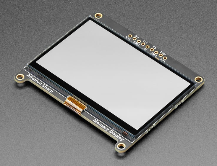
One of the highest contrast LCDs you can get. To my knowledge, this is the same display used by SwissMicros for their recreations of popular HP RPN calculators. Adafruit has a nice screen breakout board that would work if I cut the bottom tabs off. Unfortunately, the display is not the same resolution as the TI-86. It works at 400×240 while the existing screen is 128×64. We can 3x all the pixel data to 384×192, but we will still be left with 16 unused pixels horizontally and 48 unused pixels vertically. There is no backlight. $45
2. ePaper Display
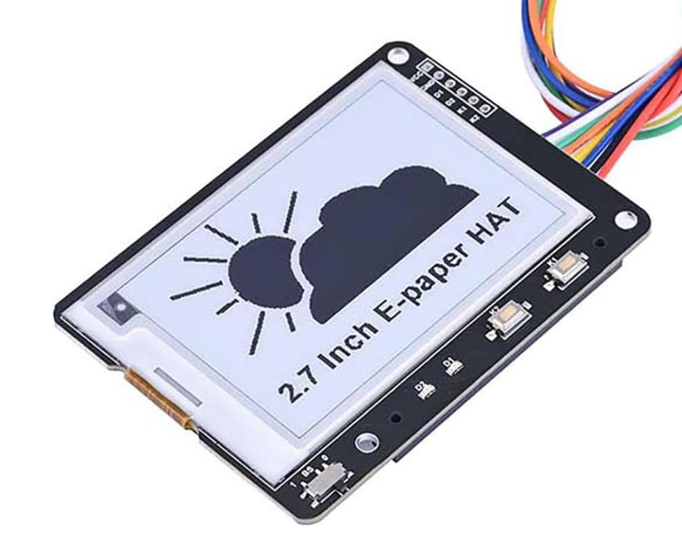
I love ePaper – great contrast and high resolution. There are a few modules on Amazon that might work. They would require cutting down the PCB, but I think it might be possible without cutting any traces. There is also a resolution challenge with ePaper since it works at 264×176. We can 2x the pixel data to get to 256×128, but that will leave 8 pixels unused horizontally and 48 unused pixels vertically. There is no backlight. $23
3. OLED Display
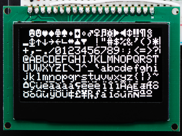
Several years ago I used a few Adafruit OLED displays for a project. I even had a 2.7” and a 2.42” display in my spare parts bin. The 2.42” model is a good fit with the TI-86. Even better, it is the same native resolution as the TI-86: 128×64 pixels. Since the display is made up of LEDs that emit light there is a natural backlight effect. $40 at Adafruit, but similar modules can be had for $15 on Amazon.
In summary, the Sharp display is cool, but it doesn’t check the box of a dramatic increase in readability over the existing display. I’ll save it for a future project. The ePaper display is nifty, but I would need to modify either the display PCB, the calculator case, or both. Again, an interesting future project but not an easy first iteration. The OLED display checks all the boxes of (a) huge increase in readability, (b) no resolution difference to deal with, and (c) drop-in fit using an adapter with the existing chassis. We’re going OLED…
Decision: Which microcontroller?
How should we read out the TI screen data, transform it, and send it to the OLED display? We’re going to run with a Raspberry Pi Pico 2. There is a laundry list of reasons:
- Lots of memory on board, so we can hold data for the entire screen in a buffer
- Loads of community support
- Reasonably low power utilization, and decent deep sleep features in the Pico 2
- Good support for C programming, which I haven’t tried on the Pico yet
- I want to learn more about the programmable I/O (PIO) features
Other good options would be an ESP32 or STM32.
First step: Get the OLED display working with the Pico
Our goal here is just to get the Pico sending SPI data out to to the OLED screen and displaying it. The screen uses a SSD1305 chip to read in SPI or I2C data and output it to the OLED display. We will use SPI, with the following pins:
- GPIO17 >> SPI Chip Select
- GPIO18 >> SPI Clock
- GPIO19 >> Master Out (MOSI)
- GPIO20 >> Screen Data/Command Select
- GPIO21 >> Screen Reset
Adafruit provides a lot of great libraries for the OLED screen. I pulled from their code on Github to create a minimum working set of code in C for the Pico. As a proof of concept, I had it output a checkerboard of alternating on and off pixels.
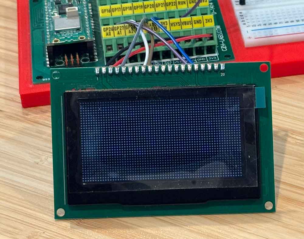
With that, we can output what we want to the screen. Now, let’s plug in the TI-86.
Next: Reading in the TI-86 screen data
We can use the test rig calculator that we built in the last blog installment and start working to read the screen data into the Pico.
The screen data lines were running at almost 6V. It looks like they tend to run with the battery voltage? Any way you slice it, the voltage is too high for the pins on the Pi Pico. Usually you would throw a level shifter in here to bring ~5V values down to 3.3V. The problems is that most level shifters won’t go above 6V according to their data sheets. We can figure out a permanent problem to that later, but for now we can solve it temporarily with two resistors acting as a voltage divider on each line – just cut the voltage in half and hope the Pico can still see it.
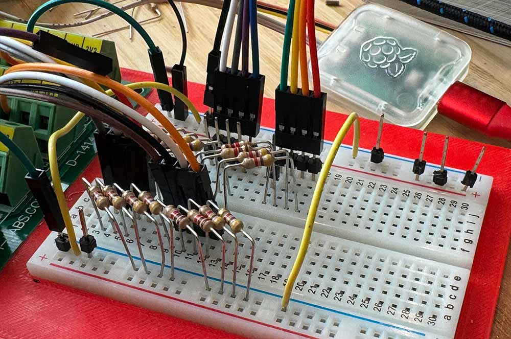
We are connecting the following lines from the TI-86 and reading in the following signals:
- GND >> GND
- Digital In 1 (DI1) >> GPIO 2
- Digital In 2 DI2 >> GPIO 3
- Digital In 3 DI3 >> GPIO 4
- Digital In 4 DI4 >> GPIO 5
- Shift Clock Pulse (SCP) >> GPIO 6
- Latch Pulse (LP) >> GPIO 7
- Digital IO 1 (DIO1) >> GPIO 8
- Frame (FR) >> Not connected (unless we need it)
One of the reasons to use a Pi Pico was to gain experience with the programmable I/O (PIO) units. The Pico 2 has 12 PIO state machines, organized into three blocks of four. There are loads of limitations to the PIOs, including instruction set limitations, a limit of 32 instructions, limited registers, and more. On the upside, you can use the PIOs to asynchronously control hardware pins, reading in or reading out information using DMA. That is what we are going to use to bring in the TI screen data.
Here is V1 of the PIO code to read in a line of data:
.program display_input
; ---------------------------------------------------------
; Reads 4-bit parallel data (D1–D4) on each falling edge of SCP.
; Waits for LP high (new line start), captures 32 samples × 4 bits = 128 bits.
; Raises IRQ 0 after each line.
;
; Host (C code) must:
;   - Set IN base to D1 (lowest-numbered of D1..D4, consecutive pins)
;   - Enable autopush with threshold = 32 bits
;   - Configure shift direction as needed
; ---------------------------------------------------------

.define SCP_PIN  4   ; Shift clock pulse (sample when LOW)
.define LP_PIN   5   ; Latch pulse (start of line)
.define DIO_PIN  6  ; Frame pulse

.wrap_target
start:
    wait 1 pin DIO_PIN
    jmp start_line

wait_lp_high:
    wait 0 pin LP_PIN     ; ensure we observe a fresh rising edge
    wait 1 pin LP_PIN     ; Wait for LP to go HIGH (start-of-line)
    wait 0 pin LP_PIN     ; ensure we observe a fresh rising edge

start_line:
    set y, 31             ; 32 samples per line

sample_loop:
    wait 0 pin SCP_PIN    ; Wait for SCP falling edge
    in pins, 4            ; Read 4 bits (D1..D4)
    wait 1 pin SCP_PIN    ; Wait for SCP to return HIGH
    jmp y--, sample_loop

line_done:
    irq 0                 ; Signal to host: one line complete
    jmp wait_lp_high
.wrap
The PIO reads a full line of data in, moves it to memory using DMA, then fires an interrupt to tell the main program that new data is available. It then waits for the next signal that a new line has begun. Piece of cake.
Next: Put the data on the screen
So, we now have a full frame of data loaded into memory using DMA. We will need to transform it to a different format and ship it out to the display using SPI.
I’m not going to dwell on this step here, since everything will be documented in the code when I get it uploaded to Github. Suffice it to say, this was probably the hardest part of the project. The display chip has a very specific format and will display garbage, or nothing at all, if you get it wrong. This was the point that the big oscilloscope came out. It was also the peak mess on my workbench.
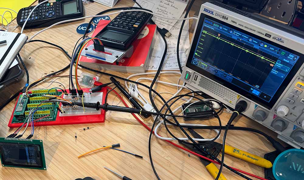
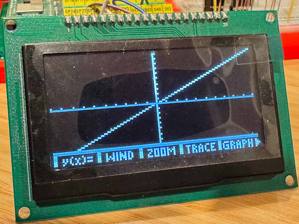
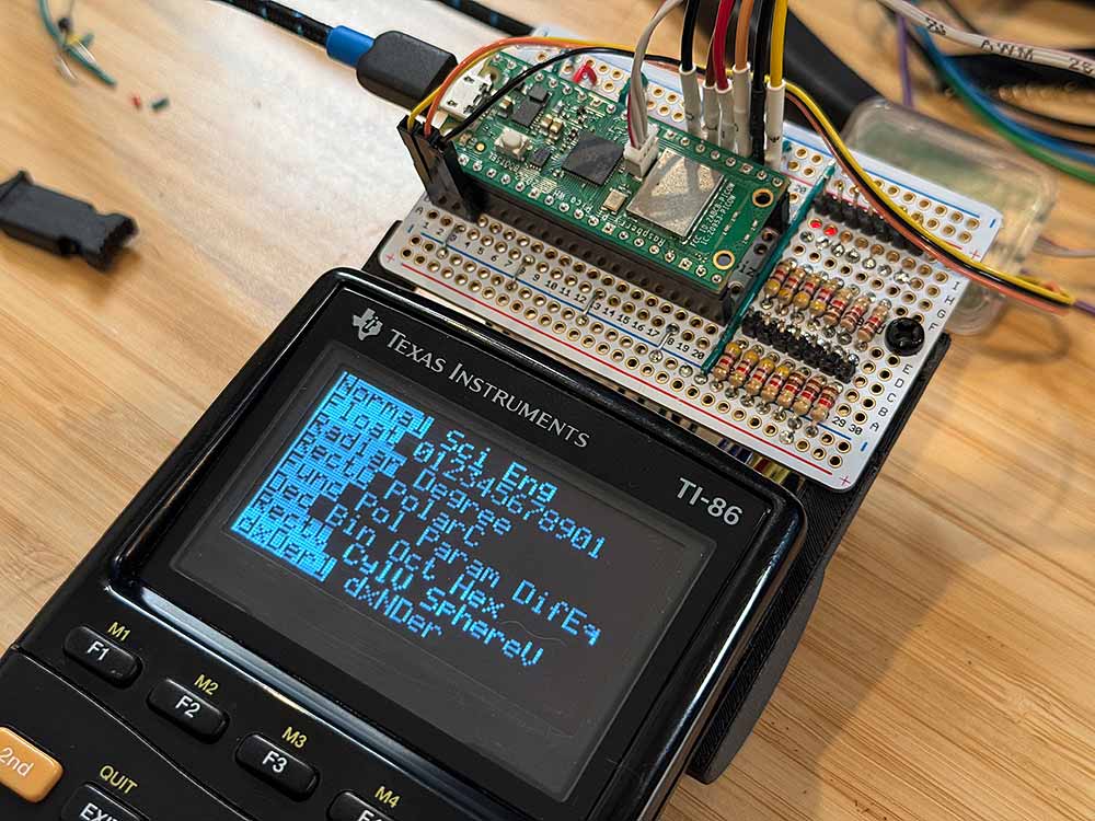
Eventually there were signs of life on the OLED display. With a few more tweaks the TI-86 screen finally appeared. At this point, we have a working prototype.
Next: Put the screen in the TI-86
We’re going to create a new test rig for integration. Time to hit up eBay and get another TI-86 with screen issues as a sacrifice for the greater good…
While the new OLED display physically fits into the TI-86 chassis, it is going to need some kind of retainer around it for ideal positioning. This is a pretty simple matter with CAD and a 3D printer, but the devil is definitely in the details. Here is the stack of attempts as we iterated toward perfection:
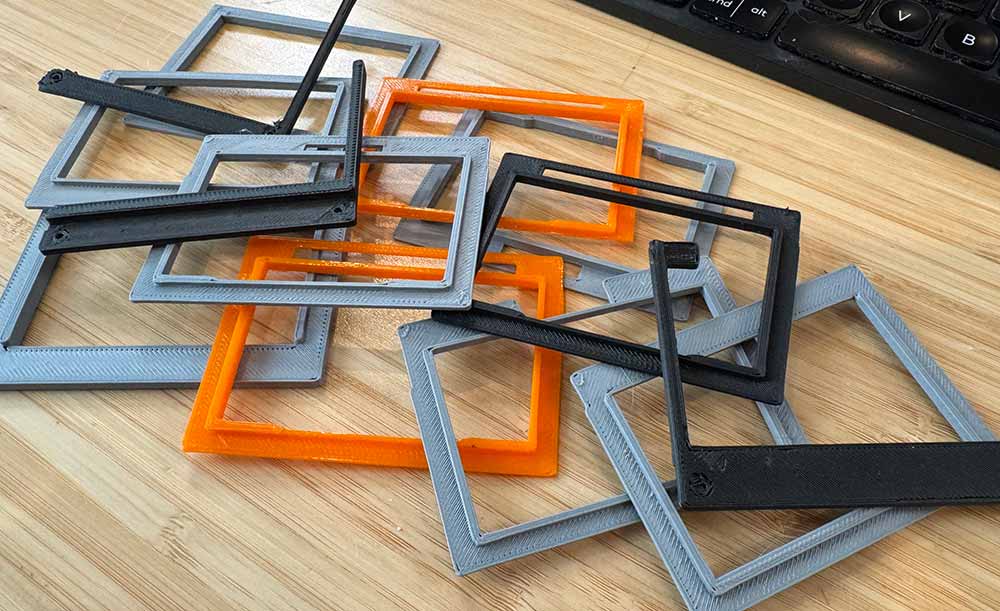
This was a classic 3D printing journey. You get the measurements 98% right straight out of the gate. Then, wait, it turns out there is something else sticking out of the calculator shell a bit. Cut that in on the frame. Now, the display is sitting a bit too close to the display. Dial that back. Oops, too far, it needs to be somewhere in the middle. Take half a millimeter out. With time it all came together.
I ended up with one piece to surround the OLED display for fit into the chassis and a second piece to apply pressure from the back calculator shell to keep the screen positioned. I think it looks pretty good in the end.

It is important to note that, while the screen is the same resolution and about the same size, vertically the display area is a bit smaller. I am not opposed to that here, but might be food for thought in the future. A larger OLED display might fit, but the controller board for it would not fit.
Next: Finalize test rig hardware
A Pi Pico was mounted to a breadboard alongside a network of voltage dividers for the digital signals. One set of power rails was from GND/VCC on the TI-86. This was at around 6V. The other power rail was from the microcontroller regulator and was at 3.3V. For now, the Pi Pico would power the display and the Pico would be powered by USB, although I left pins available to put a buck converter on temporarily for mobile operation.
Seven digital signals and two power lines were brought out of the calculator rig. Five digital lines and two power lines were sent out to the screen.
We’re in business.
The Future
There is a laundry list of to-dos for the final TI-86 integration:
1. Clean up the code, since it is a wild mess.
2. Put a proper level converter in for the digital signals. The voltage divider works, but it is a hack. If the signals follow battery voltage then there is also no guarantee they will work when the voltage gets low. Am thinking of using a 74HC4050 since the inputs will handle 6V+.
3. I want the Pico to be able to turn the OLED screen on. Since the current is higher than the GPIO pins can handle, will need to have some kind of circuit to switch it. MOSFET?
4. Will need to be able to put the Pico 2 into deep sleep when not in use and wake on input. The voltage supplied to the screen is constant and not switched by the calculator, so I need to handle all of that.
For now, I will just enjoy a working protype of an OLED TI-86. Cheers…
